
September 2026 GIAG Proposal for Generation HVDC FACTS and High Impact Large Loads
SPP is proposing a broader and more disciplined dynamic-modeling framework for a grid that increasingly depends on converter-based resources, merchant HVDC facilities, dynamic reactive devices, and High Impact Large Loads. The September 2026 GIAG presentation does more than add technical tests. It reframes model development as a lifecycle obligation that begins with the first request, matures through agreement and commissioning, and continues after commercial operation.
The proposal is still moving through the SPP stakeholder process. Its direction is nevertheless clear: a model will need to be accurate on its own, consistent with companion models, supported by repeatable test evidence, verified against facility parameters, and maintained as the plant changes.
Why SPP Is Expanding the Framework
SPP’s stated objective is consistent, accurate, and reliable representation of HVDC systems, dynamic reactive resources, and HILLs across PSS/E, TSAT, and PSCAD. That objective reflects a planning environment in which fast converter controls, protection logic, grid strength, and load ride-through behavior can materially affect both regional stability studies and project-specific conclusions.
The scope reaches well beyond a conventional generator model. The Revision Request package identified in the presentation would touch Tariff Attachments V, AY, AX, AQ, and BA; the Model Development Procedure Manual; the SPP HVDC Planning Manual; and Business Practice 7850. SPP also proposes renaming its Generating Facilities Modeling Requirements Manual as the Dynamic Modeling Requirements Manual and broadening the associated study agreement.
The Proposed Manual Architecture
The presentation describes a manual organized around scope and applicability, the model-submittal process, model requirements, model quality and performance testing, and a model checklist. Requirements are divided among standard-library models and user-defined models for PSS/E, TSAT, and PSCAD. Four appendices support that structure.
For project teams, this is an important governance change. Modeling requirements that may once have been managed as separate software deliverables are being brought into one documented process with common evidence, checkpoints, and ownership expectations.
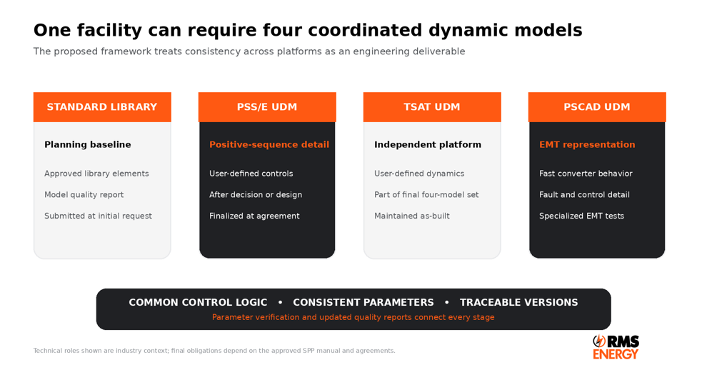
Figure 1 The proposed model set spans positive-sequence and electromagnetic-transient study environments
One Facility Four Model Types
A standard-library model establishes the planning baseline. PSS/E and TSAT user-defined models provide platform-specific positive-sequence detail, while the PSCAD user-defined model provides the electromagnetic-transient representation needed for fast converter controls, protection interactions, unbalanced conditions, phase-angle changes, and subsynchronous phenomena.
The challenge is not simply producing four files. Every representation must describe the same facility: ratings, control modes, limits, protection, plant response, equipment status, and point-of-interconnection behavior must reconcile. SPP’s recurring requirements for parameter verification and updated test reports reinforce that expectation.
Model Submission Becomes a Lifecycle Process
The proposed workflows differ by asset class, but they follow a common pattern. An initial standard-library model supports early planning. More detailed user-defined models arrive after a decision point or during design. Finalized models support the agreement. As-built models are due at commercial operation. After COD, changes to the facility must flow back into the models, quality reports, and parameter-verification record.
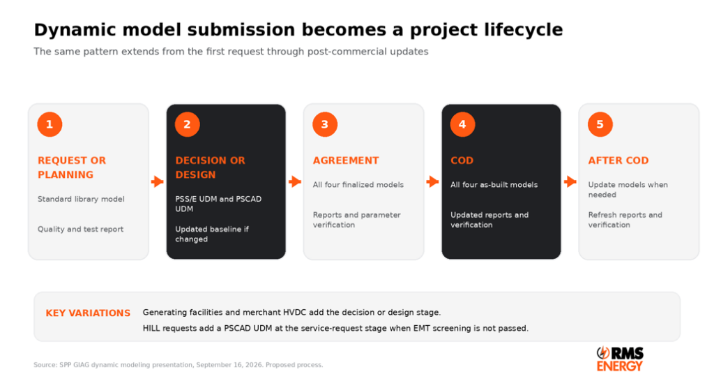
Figure 2 Common lifecycle and the principal variations by resource type
Generating Facilities Including HVDC Tie Lines
At the interconnection-request stage, the developer would submit a standard-library model with a model-quality and test report. After the Interconnection Customer Selection decision point, the package expands to PSS/E and PSCAD user-defined models with their reports, plus an updated standard-library model when changes occur. The GIA stage requires all four finalized models, a quality and performance report, and parameter verification. COD requires the four as-built models, and post-COD changes require corresponding model and evidence updates.
Merchant HVDC Facilities
Merchant HVDC follows the same technical progression but aligns it to planning studies, design studies, the interconnection agreement, COD, and post-COD maintenance. The design-study stage introduces PSS/E and PSCAD user-defined models. The agreement stage adds the finalized TSAT model and parameter verification. This sequencing gives SPP progressively greater control detail as the design becomes fixed.
Dynamic Reactive Resources
Transmission-connected synchronous condensers and FACTS devices begin with a standard-library model and supporting quality report. By the interconnection agreement, the facility would provide all four finalized models, the quality and performance report, and parameter verification. The same as-built and post-COD maintenance expectations then apply.
High Impact Large Loads
HILLs follow a service-request path. The initial submission includes a standard-library model and quality report. A PSCAD user-defined model and report are also required at that stage for requests that do not pass EMT screening. At the service agreement, the customer would provide all four finalized models, quality and performance evidence, and parameter verification, followed by as-built and post-COD updates.
This is consequential for data centers and other electronically controlled loads. Their dynamic representation can no longer be reduced to a static megawatt and power-factor assumption when ride-through, transfer logic, backup generation, or converter controls determine how the load responds to grid events.
Quality Testing Is Technology Specific
The presentation lists a broad family of quality and performance tests. Some verify basic numerical behavior, such as initialization. Others challenge the model with voltage, frequency, active-power, reactive-power, phase-angle, or fault disturbances. The objective is not only to show that a model runs, but that it responds in a stable, credible, and technology-appropriate manner.
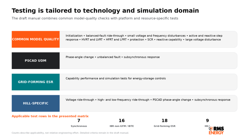
Figure 3 Test families presented for the proposed Dynamic Modeling Requirements Manual
What the Test Families Are Intended to Reveal
- Initialization testing checks whether the model starts from the solved operating point without unacceptable transients, drift, or numerical failure.
- Small-disturbance and step-response tests expose control gains, limiters, deadbands, recovery behavior, and active or reactive control modes.
- Ride-through tests examine whether modeled controls and protection remain connected and recover through specified voltage or frequency excursions.
- Protection verification links model response to the facility’s intended protection settings and trip logic.
- SCR, unbalanced-fault, phase-angle-change, and subsynchronous tests challenge converter behavior under weak-grid, asymmetric, or fast electromagnetic conditions.
- Resource-specific HILL tests focus on the aggregate response of controlled load, power electronics, transfer schemes, and associated protection.
The presentation identifies the test names and applicability. The final manual will control the precise disturbance magnitudes, durations, pass or fail criteria, initialization tolerances, data channels, and reporting format. Project teams should avoid treating the names alone as complete test specifications.
How Applicability Changes by Resource Type
SPP’s matrix distinguishes four categories: synchronous generating facilities and transmission-level synchronous condensers; inverter-based resources, non-grid-forming energy-storage resources, and inverter-based transmission equipment; grid-forming energy-storage resources; and HILLs. Inverter-based transmission equipment includes converter-interfaced devices such as SVCs, STATCOMs, and HVDC interconnections and ties.
The tables below reproduce the applicability shown in the GIAG presentation. They indicate whether a test row applies, not the relative effort, number of operating points, or number of simulation cases required.
General Quality and Performance Tests
| Ref | Test | Sync | IBR / non-GFM ESR / IBTE | GFM ESR | HILL |
| 5.1.1 | Model Initialization Testing | Yes | Yes | Yes | Yes |
| 5.1.2 | Balanced Fault Ride-Through | No | Yes | Yes | No |
| 5.1.3 | Small Voltage Disturbance | Yes | Yes | Yes | No |
| 5.1.4 | Small Frequency Disturbance | Yes | Yes | Yes | No |
| 5.1.5 | Voltage or Power Factor Step Response | Yes | Yes | Yes | No |
| 5.1.6 | Active Power Step Response | Yes | Yes | Yes | No |
| 5.1.7 | High-Voltage Ride-Through | No | Yes | Yes | No |
| 5.1.8 | Low-Voltage Ride-Through | No | Yes | Yes | No |
| 5.1.9 | High-Frequency Ride-Through | No | Yes | Yes | Yes |
| 5.1.10 | Low-Frequency Ride-Through | No | Yes | Yes | Yes |
| 5.1.11 | Protection Verification | Yes | Yes | Yes | No |
| 5.1.12 | Short Circuit Ratio | No | Yes | Yes | No |
| 5.1.13 | Reactive Power Capability | No | Yes | Yes | No |
| 5.1.14 | Large Voltage Disturbance | Yes | No | Yes | No |
Specialized PSCAD Resource and HILL Tests
PSCAD and Resource Specific Tests
| Ref | Test | Sync | IBR / non-GFM ESR / IBTE | GFM ESR | HILL |
| 5.2.1 | Phase Angle Change | No | Yes | Yes | Yes |
| 5.2.2 | Unbalanced Fault | No | Yes | Yes | No |
| 5.2.3 | Subsynchronous | No | Yes | Yes | No |
| 5.3 | ESR Controls Capability and Performance | No | No | Yes | No |
| 5.4.1 | HILL Voltage Ride-Through | No | No | No | Yes |
| 5.4.2 | HILL High-Frequency Ride-Through | No | No | No | Yes |
| 5.4.3 | HILL Low-Frequency Ride-Through | No | No | No | Yes |
| 5.4.4 | HILL Phase Angle Change for PSCAD UDM | No | No | No | Yes |
| 5.4.5 | HILL Subsynchronous | No | No | No | Yes |
Three Practical Readings of the Matrix
1. Grid-forming storage receives the broadest coverage. The presentation marks every general test, every PSCAD-specific test, and the dedicated ESR control test as applicable. That reflects the central role of grid-forming controls in voltage and frequency response.
2. IBR and IBTE testing emphasizes converter behavior. Balanced-fault ride-through, voltage and frequency ride-through, short-circuit ratio, reactive capability, phase-angle, unbalanced-fault, and subsynchronous tests are all applicable.
3. HILL testing is narrower but purpose-built. The matrix focuses on initialization, frequency behavior, PSCAD phase-angle response, and a dedicated group of HILL voltage, frequency, and subsynchronous tests.
Evidence Must Be Reproducible
A credible test package should preserve the model version, software version, network equivalent, operating point, disturbance definition, channels, protection status, assumptions, and expected result. Plots without an auditable case file or with parameters that differ from the submitted model are unlikely to support efficient review. A common test harness and controlled parameter register can reduce discrepancies across PSS/E, TSAT, and PSCAD.
Parameter Verification Connects the Model to the Facility
Parameter verification appears at the agreement, COD, and post-COD stages. That cadence matters. Design values may change during procurement, factory testing, controller tuning, or commissioning. The final model package should reconcile those changes to approved equipment data and field settings, document any justified differences between simulation platforms, and retain an approval trail.
A Separate Dynamic Model Quality Study Agreement
SPP also presented a 14-article Dynamic Model Quality Study Agreement. The agreement is not proposed as a pro forma standard agreement under the SPP Open Access Transmission Tariff. Instead, it would serve as a separate template used solely for a dynamic-model quality study.
Article 3 identifies a $10,000 deposit. That amount is a deposit rather than a statement of final study cost. Project sponsors should therefore plan for both the upfront payment and the possibility of additional actual costs under the final agreement terms.
The MOD-026-2 Governance Question
SPP asked whether the Dynamic Modeling Requirements Manual should serve only as the interconnection manual or also as the compliance manual for MOD-026-2. A single document could improve consistency, but it must clearly distinguish interconnection screening, model validation, NERC evidence, periodic verification, and operating-model maintenance.
What Project Teams Should Do Now
1. Establish cross-platform model governance. Inventory all four models, owners, software versions, dependencies, and licenses. Maintain one register for ratings, controls, limits, delays, and protection thresholds.
2. Design the test plan before model completion. Turn each applicable matrix row into cases, operating points, evidence, plots, reproducible files, and requirement-to-result traceability.
3. Plan as-built validation and change control. Reconcile final controls and protection after commissioning. Firmware, tuning, equipment, or topology changes should trigger a review across every model and report.
4. Treat vendor coordination as a schedule risk. Address encrypted libraries, compiler support, software packaging, source protection, and vendor troubleshooting obligations in procurement terms.
5. Screen EMT needs early. HILLs that do not pass screening need a PSCAD UDM at the service-request stage. Converter-heavy generation, HVDC, FACTS, and storage also need time for EMT development and benchmarking.
RMS Energy Perspective
RMS Energy views the SPP proposal as a necessary response to dynamic behavior distributed across generators, transmission devices, storage controls, and large electronic loads. The central development is consistency through time and across tools.
Model governance, parameter traceability, and a platform-neutral test plan can improve interconnection review, commissioning, and future updates. A disciplined model set also becomes a reusable asset for design, tuning, equipment selection, operating limits, event analysis, and compliance.
Learn more about how RMS Energy supports complex transmission projects through our T&D Engineering and Consulting Services
Stakeholder Schedule
Working-group review spans the third and fourth quarters of 2026. Listed approvals are MDAG on October 20, TWG on October 27, ORWG on November 5, MWG on November 17, RTWG on November 19, and MOPC in January 2027. Stakeholder comments were requested by October 5, 2026.
#RMSEnergy #SPP #DynamicModeling #GridReliability #PSCAD #LargeLoads