
Large Load Ride Through and Storage as Transmission
The PJM Planning Committee’s September 8, 2026 meeting highlighted two initiatives with significant implications for utilities, data-center developers, transmission owners, storage developers and engineering consultants. PJM presented proposed voltage and frequency ride-through requirements for Large Computational Loads and an updated framework for using battery energy storage as a transmission-only asset.
Although the initiatives address different challenges, they point to the same conclusion: grid-connected facilities can no longer be evaluated only by size and point of interconnection. Their controls, disturbance response, operating limitations and modeled behavior are becoming central to transmission planning.
Large Computational Loads May Face Ride Through Requirements
Recent events involving the simultaneous disconnection of large amounts of data-center load during and after normally cleared transmission faults have raised reliability concerns across the industry.
A multi-gigawatt load reduction may initially appear helpful to the grid. However, the sudden loss of that much demand can create frequency and voltage excursions, followed by a second disturbance when the load attempts to restore. The behavior of uninterruptible power supplies, power-electronic equipment, cooling systems, backup generation and load-transfer controls can therefore have system-wide consequences.
In response to FERC’s June 18, 2026 Show Cause Order in Docket EL26-67-000, PJM presented preliminary voltage and frequency ride-through requirements for Large Computational Loads.
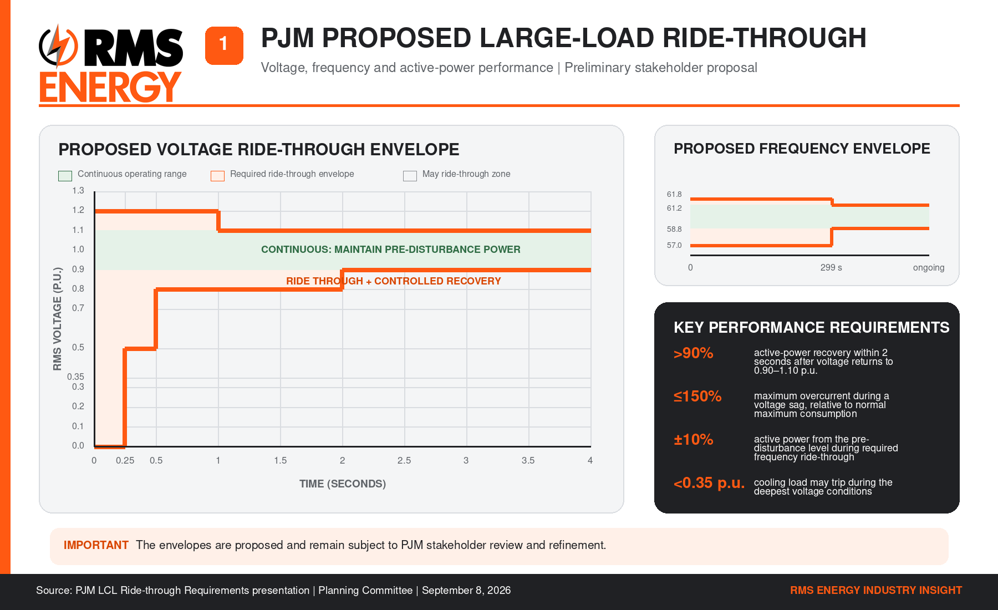
Figure 1 PJM’s proposed large-load ride-through framework. The envelopes and performance requirements remain subject to stakeholder review.
Proposed Voltage Performance
PJM’s preliminary voltage ride-through framework would establish a continuous operating range between approximately 0.90 and 1.10 per unit voltage. Within this range, a large computational load would generally be expected to maintain its pre-disturbance active-power consumption.
During more severe voltage deviations, some power reduction may be permitted, but the load would be required to recover to more than 90% of its pre-disturbance level within two seconds after voltage returns to the continuous operating range.
• Limit overcurrent during a voltage sag to 150% of the maximum current consumed during normal operation.
• Allow certain cooling loads to trip when voltage falls below 0.35 per unit.
• Define voltage and time boundaries within which the facility must remain connected.
• Establish post-fault active-power recovery expectations.
Proposed Frequency Performance
PJM also proposed a continuous frequency operating range of approximately 58.8 to 61.2 Hz. Within this range, large computational loads would be expected to maintain their pre-disturbance power consumption.
For broader frequency excursions requiring ride-through, the load would generally need to remain within 10% of its pre-disturbance active-power consumption. The preliminary short-duration envelope extends to approximately 57.0 to 61.8 Hz.
Implications for Data Center Development
These requirements would represent more than a tariff-compliance exercise. They could directly affect facility electrical design, equipment specifications, control settings, modeling and commissioning.
Large-load developers may need to demonstrate that the combined facility – not just an individual component – responds acceptably during grid disturbances. Coordinated analysis may need to address:
• Utility service and point-of-interconnection voltage
• UPS and power-conversion controls
• Static transfer switches and protection settings
• Cooling and auxiliary-load behavior
• Backup generation and load-transfer schemes
• Post-disturbance load restoration and ramp rates
• Aggregate facility response during transmission faults
Validated steady-state, dynamic and potentially electromagnetic transient models will become increasingly important. A facility that appears acceptable in a power-flow study may still create reliability concerns if large blocks of power-electronic load disconnect or restore simultaneously.
PJM’s presentation anticipated continued manual and tariff review during fall 2026, a Show Cause filing in November 2026, development of ramp-rate requirements in the first quarter of 2027, and further work on the design envelope and stakeholder endorsement during 2027.
Battery Storage as a Transmission Solution
The second major development was PJM’s updated Storage as a Transmission Asset framework. Under the proposal, a battery storage facility could be selected through the Regional Transmission Expansion Plan process when it is the most cost-effective solution to an identified transmission need.
The asset would be treated as transmission infrastructure rather than as a merchant generation or market resource. PJM indicated that these projects would most likely address relatively small, localized reliability needs and would typically have durations of four hours or less.
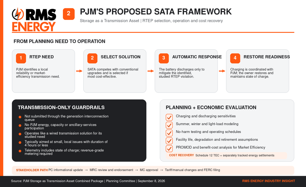
Figure 2 PJM’s proposed Storage as a Transmission Asset framework, including the RTEP selection path, operational guardrails and planning evaluation.
How the SATA Model Would Work
PJM’s framework establishes several important boundaries:
• A SATA facility would not participate in PJM’s energy, capacity or ancillary-services markets.
• It would not enter through the generation interconnection queue.
• Its operation would be limited to resolving the specific RTEP violation for which it was selected.
• Discharge would occur automatically or as designed when the identified transmission condition occurs.
• Recharging would be coordinated with PJM.
• The asset owner would maintain the required state of charge and operational readiness.
• Telemetry would generally follow energy-storage-resource requirements and include state-of-charge information.
• Revenue-grade metering would be required.
The objective is for the storage facility to produce an operational and market effect comparable to a conventional wired transmission solution.
Planning and Economic Evaluation
A SATA proposal would still need to demonstrate that it is preferable to conventional transmission alternatives. The planning analysis could include:
• Charging and discharging sensitivities
• Facility sizing and response-time requirements
• Summer, winter and light-load modeling
• No-harm testing
• Charging impacts on surrounding transmission facilities
• Operating schedules and state-of-charge assumptions
• Expected facility life, degradation, replacement and retirement
• Capital and operating costs
• Additional reliability or economic benefits
PJM also clarified that storage-based solutions could be evaluated within the Order No. 1000 Market Efficiency process. In that application, PROMOD production-cost analysis would be used to determine whether the storage solution can reduce congestion and provide net economic benefits to customers.
Even when evaluated for market efficiency, the SATA facility would operate only as necessary to address the transmission condition studied by PJM. It would not be dispatched as a merchant resource seeking market revenue.
Cost Recovery and Settlements
The current framework contemplates cost-of-service recovery through Schedule 12 Transmission Enhancement Credits. Energy injections and withdrawals associated with charging and discharging would be processed through normal energy settlements.
These amounts would be tracked separately and accounted for in the asset owner’s subsequent transmission revenue requirement to avoid double compensation. PJM’s presentation anticipated additional stakeholder review during fall 2026, followed by conforming tariff and manual language and a potential FERC filing.
Source materials PJM Planning Committee Agenda; PJM LCL Ride-through Requirements presentation; and PJM Storage as Transmission Asset Combined Package Summary, all dated September 8, 2026.
A Common Planning Theme
Large computational loads and transmission-only storage sit on opposite sides of the power balance: one consumes electricity, while the other can absorb or inject it. Yet PJM’s proposals apply the same fundamental principle to both. Grid-connected facilities must perform in accordance with the assumptions used to plan the transmission system.
For large loads, this means remaining connected through defined disturbances and restoring demand in a controlled manner. For transmission storage, it means operating only within the charging, discharging and state-of-charge conditions that justified the asset’s selection as a transmission solution.
In both cases, accurate models and clearly defined control behavior will be essential. Planning studies must represent how these facilities actually respond, not simply how developers expect them to respond.
| Development | Core planning question | Primary implication |
| Large computational loads | Will the facility remain connected and recover predictably after a grid disturbance? | Equipment controls and validated aggregate models become central to interconnection readiness. |
| Storage as transmission | Can a battery resolve the identified RTEP need more cost-effectively than a conventional upgrade? | The storage asset operates only for its studied transmission function and does not participate as a merchant resource. |
RMS Energy Perspective
These developments point toward a more performance-based planning environment in PJM. For data-center developers, ride-through capability should be considered early in site selection, utility coordination, equipment procurement and interconnection studies. Waiting until commissioning to evaluate aggregate facility response could expose a project to equipment changes, control modifications or schedule delays.
For transmission and storage developers, the SATA framework creates another potential pathway for battery deployment, but one that requires a different commercial and technical strategy from a conventional merchant BESS project. Success will depend on demonstrating that the solution can reliably address a defined transmission need while remaining cost-effective against traditional wires alternatives.
What to Watch
• Final voltage and frequency ride-through envelopes
• Large-load ramp-rate and restoration requirements
• Dynamic and EMT modeling expectations
• Model validation and compliance-testing requirements
• SATA eligibility and competitive-planning procedures
• Storage degradation, augmentation and lifecycle assumptions
• Cost allocation, energy settlements and operational control
PJM’s direction is increasingly clear: data centers and battery storage are becoming integral components of how the regional grid is modeled, designed and operated.
#PJM #DataCenters #LargeLoads #GridReliability #EnergyStorage #BESS #TransmissionPlanning #PowerSystems #RMSEnergy