

Material Modification requirements across all seven US ISO and RTO regions
A solar or battery project completes its interconnection study. Procurement then identifies a different inverter, an updated firmware release, or a replacement plant controller. The point of interconnection and contracted MW remain the same. Can the project proceed with the change?
The answer depends on the electrical impact, the project’s stage, and the applicable regional process. Developers should establish the review path before committing to a configuration that differs from the studied plant. A change can require notification, revised models, additional analysis, or a new interconnection request—even when the export limit is unchanged.
For RMS Energy, the practical priority is to connect equipment decisions with interconnection engineering early enough to protect procurement, commissioning, and commercial-operation schedules.
The study represents a specific electrical configuration
An inverter’s MW rating describes only part of its behavior. The plant controller, inverter controls, protection, collector system, and transformer characteristics together determine the plant’s response at the point of interconnection (POI). NERC’s EMT guidance describes how interactions between plant-level and inverter-level controls can affect disturbance recovery. [1]
| Proposed change | Engineering questions to resolve |
| Inverter make or model | Do reactive capability, current limits, fault response, protection, or recovery behavior change? |
| Firmware or control settings | Does the update alter ride-through, current priority, control modes, or response timing? |
| Plant controller or tuning | Do voltage regulation, droop, deadbands, gains, measurement filtering, or communication delays change? |
| Plant configuration | Do unit count, transformer or collector impedances, operating modes, or the export-limiting scheme change? |
The assessment should be proportional to the change. A software update affecting only reporting may have a different consequence from one that changes fault recovery. The OEM’s change description and a comparison against the studied configuration help establish that difference.
Material Modification is a formal determination
A model update, a Material Modification review, and a restudy are different actions. Correcting a model may improve its representation of an unchanged plant. Changing hardware or controls may alter the plant itself. The operator then applies the governing criteria to determine whether the proposed change is permissible and what analysis is needed.
Across the FERC-jurisdictional regions, Material Modification provisions commonly address effects on other interconnection requests, reliability, or expressly restricted project changes. Their definitions and exceptions differ. ERCOT applies a separate Texas framework for generation interconnection and modification. [2–11]
A non-material finding does not necessarily mean no further work. The project may still need revised studies, models, facility designs, agreement amendments, or commissioning evidence. Conversely, submission of a modification request does not automatically mean the project loses its queue position.
Requirements across the seven regions
The following comparison focuses on utility-scale generation and storage. The applicable queue cycle, facility category, tariff transition rules, and executed agreement determine the specific route. The cited requirements should be checked against the project’s own milestones before implementation.
CAISO
CAISO evaluates project changes through its Material Modification Assessment (MMA) process, with specified exceptions and a separate Permissible Technological Advancement pathway. Its queue review considers effects on other requests’ costs and timing. A non-material change can still require a facilities reassessment and updated cost or schedule estimates. [2]
The Generator Management BPM provides a narrow inverter exception: a manufacturer-only change can avoid MMA when technology, electrical characteristics, inverter number, and size remain unchanged, and the Participating Transmission Owner agrees that dynamic analysis is unnecessary. Notice and inverter data are still required. This is not a blanket exemption for an inverter swap. [2]
After COD, CAISO evaluates changes to capacity and electrical characteristics under its post-COD framework. Developers should identify the applicable procedures, including Appendix DD or Appendix KK, rather than assume every cluster has identical modification windows. [2,3]
ERCOT
ERCOT’s Generator Interconnection or Modification (GIM) process applies under Planning Guide Section 5.2.1. Its triggers include a non-in-kind inverter or specified equipment replacement associated with a facility rated at least 10 MW. Control changes can also require GIM when the review determines further study is necessary. [4]
During continuing operations, Section 5.5(6) requires prior ERCOT and interconnecting TSP review of IBR equipment or settings changes that affect dynamic response at the POI. The submission includes the proposed dynamic model, before-and-after model-quality-test overlays, and simulation files. Outcomes include acceptance without a stability study, a limited stability study, a GIM request, or rejection. ERCOT may authorize temporary implementation to address a performance deficiency. [4]
Between completion of the Full Interconnection Study and initial synchronization, changed assumptions must be reported to ERCOT and the lead TSP. Changes that could materially alter the study conclusions require updated study elements and may delay synchronization. [4]
ISO New England
PP5-6 Appendix E, Procedures for Material Modification Determinations, provides implementation guidance for the modification-review procedures in OATT Schedules 22, 23, and 25. The screening threshold depends on whether the executed Cluster Study Agreement has been submitted. Before that milestone, listed changes to technical parameters, step-up transformer impedance, interconnection configuration, and POI are not deemed material under the appendix. After it, proposed changes are evaluated under the applicable materiality rules and technical screens. [5]
The post-agreement framework includes as purchased data, as built/as tested data, and changes to existing facilities. As purchased data must be submitted at least 180 Calendar Days before Initial Synchronization and reviewed before synchronization is permitted. As built/as tested data must be submitted before Commercial Operation and reviewed before the facility is allowed to become commercial. These are engineering review milestones that procurement and commissioning schedules must accommodate. [5]
For dynamic-model or voltage-control changes, Appendix E screens for the absence of voltage or dynamic-stability problems that the change may adversely affect in base cases for the most severe N-1 and N-1-1 contingencies. The new models must provide similar or better dynamic voltage and stability performance in simulations of a few severe faults. For facilities requiring a PSCAD model, the PSCAD-change screen likewise calls for similar or better performance for the most severe N-1 and N-1-1 contingencies. [5]
For impedance changes, the short-circuit screens address total impedance and X/R ratio, and confirmation that fault duty at the interconnecting bus does not increase. Stability screening considers similar or better performance, including damping and angular swing. The voltage screen identifies a non-material route when the impedance change is less than 10% of the SIS impedance, the tariff power-factor requirement is satisfied, and no pre-existing voltage problem exists. A change that causes failure to meet the tariff power-factor requirement is material. These are distinct technical screens, not a universal 10% allowance for equipment substitutions. [5]
After the executed Cluster Study Agreement is submitted, significant additional study that could substantially change the interconnection design, or material cost or timing effects on equally or later queued requests, can require a new request. The appendix also identifies changes that require a new request at any stage, including increased energy or capacity capability above the request or agreement and a change from NR to CNR service. An unchanged MW rating does not replace the Appendix E assessment. [5]
MISO
For the MISO facility-modification assessment package, the supplied Facility Modification Requirements document provides the practical report and modeling instructions, referencing BPM-015 Sections 6.7.1 and 6.7.4. It directs customers to use Template Facility Modification.docx and submit the report at least 30 calendar days before the next DPP phase starts so changes can be reflected in the model update. Its FAQ describes an approximately 30-calendar-day review, which can take longer when information is incomplete or MISO or the transmission owner raises questions. The submission lead time and review duration are separate planning considerations. [7]
DPP Phase 1 submissions include an element-by-element comparison of the original and proposed configurations; revised PSS/E RAW and slider files; a one-line diagram; applicable IDV changes; and updated dynamic-model information, including current UDM and DLL files where used. The requirements specify PSS/E v35.6-compatible response files and consistent project, bus, and portal data. Applicable power-flow comparisons cover ERIS/NRIS thermal impacts and ERIS voltage impacts using the latest completed regional DPP model appropriate to the project, with shoulder and summer/peak cases and BESS charging and discharging cases. The full study package is required. Thermal steady-state analysis is not required for an inverter change, according to the document. That exception does not eliminate the other applicable reviews. [7]
DPP Phases 2 and 3 add short-circuit, transient-stability, power-factor, LVRT/HVRT, and transmission-owner Local Planning Criteria assessments. Short-circuit comparisons include three-line-to-ground, single-line-to-ground, line-to-line, and line-to-line-to-ground fault contributions at the POI. Stability work uses the applicable TSAT model package, monitors at least 10 buses out from the POI and nearby plants, and includes plots of at least 15 seconds for generator active and reactive power, POI voltage, and generator angle for synchronous machines. The complete TSAT input and output package and a results summary are required. [7]
For IBR modifications, a PSCAD model is required and must be consistent with the DYR model, as reinforced by the document’s FAQ. Reactive-performance comparisons cover leading and lagging operation from 0.95 to 1.05 p.u., including the actual DPP-case voltage, with performance reported at the high side of the main step-up transformer. LVRT/HVRT comparisons include three-phase and single-line-to-ground faults at 100% active power at the POI, subject to the document’s stated standards and applicable transmission-owner criteria. [7]
For acceptance, the FAQ describes the same or better behavior, no new Network Upgrades or cost allocations, no new or increased overloads, and no new stability-voltage issues. It states that steady-state voltage may vary by 0.01 p.u., while still meeting transmission-owner criteria. This is not a blanket tolerance for every signal or test. The document’s opening wording asks for better results; its detailed FAQ explicitly allows the same or better behavior. The report should demonstrate the applicable criteria and resolve any interpretation with MISO. [7]
The document also distinguishes timing: a POI or inverter change before the DPP Phase 1 kickoff can be handled by updating portal information without an MM report, while a POI change during the GIA phase cannot be pursued through an MM report. Multiple changes may be assessed cumulatively in one report. The facility-modification package supports the determination; the governing Attachment X provisions still control the permissible change and queue outcome. [6,7]
NYISO
Attachment HH Section 40.6.3 establishes the Facility Modification Request process, generally with a $10,000 study deposit and supporting information, including resulting model changes. Section 40.6.3.7 specifically addresses advances involving inverters, turbines, and plant supervisory controls. NYISO evaluates eligibility for its permissible-advancement pathway and may require additional studies. [8]
For an ongoing Cluster Study, the technological-change request and required supporting material must be complete at least 10 Business Days before the Customer Engagement Window closes. Later technological changes are deemed material for the remainder of that Cluster Study. Timing therefore matters even when the proposed equipment has favorable performance. [8]
A change determined to be permissible or non-material can retain queue position. For a material change, the customer may withdraw the modification or submit a new request in a subsequent cluster. Legacy-project transition provisions must also be checked. [8]
PJM
PJM’s Manual 14H Section 9.8 makes equipment-change timing explicit for the cycle process: updated equipment data may be submitted at Decision Point I; only Permissible Technological Advancement equipment changes are allowed at Decision Point II; no equipment changes are allowed at Decision Point III. Associated machine-model data must meet the applicable deadline. [9]
A permissible advancement cannot increase facility capability, change fuel type, or cause material adverse effects involving fault duty, thermal or voltage limits, or dynamic performance. If PJM accepts that classification, the change is non-material and no additional PJM study is required under that provision. [9]
After a signed ISA or GIA, or for an operating facility, Section 9.7.3 provides a different route: a change to previously studied electrical characteristics without increasing Maximum Facility Output or Capacity Interconnection Rights requires a Necessary Study request. The queue’s decision-point allowances should not be used as the post-agreement approval process. [9]
SPP
Attachment V Section 4.4 requires written notification of changes to interconnection-request information. SPP can use a Modification Request Impact Study (MRIS) to determine materiality. If additional studies are required, the tariff calls for a $60,000 deposit within five Business Days of notification, with actual costs reconciled. Resulting model updates accompany the request. [10,11]
The separate technological-advancement request must be submitted before the end of Decision Point II. SPP evaluates the request under its tariff; qualifying advancements can avoid a material finding. Other reviews may address power flow, reactive capability, fault duty, and stability. [10]
Business Practice 7250 also addresses changes to dynamic models and their parameters. A material change that the customer still wishes to pursue requires a new interconnection request. Replacement of operating generators or storage devices can fall under SPP’s replacement or retirement procedures rather than MRIS, so the route should be confirmed first. [11]
A practical example of why the review matters
Consider an illustrative 200 MW solar project that retains its export limit and POI but changes inverter model. The replacement uses different current prioritization during voltage disturbances and different recovery settings. The plant’s normal power-flow result may remain similar while its fault response changes.
The figures below use synthetic curves to illustrate comparisons between models labeled SIS and MMD. They are not project or workshop results and do not demonstrate acceptance. The slower recovery, larger overshoot, and weaker damping shown in the MMD examples warrant investigation against the applicable criteria. ISO-NE Appendix E calls for similar or better performance under its relevant screens; MISO’s requirements call for the same or better behavior under the stated assessments. MISO transient-stability submissions require plots of at least 15 seconds; these shorter illustrations are not submission-ready study plots. [5,7]
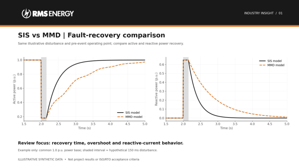
Figure 1. Illustrative active and reactive power recovery comparison. Use the same disturbance, operating point, measurement location, and power base when comparing actual model outputs.
Voltage-control benchmarking can reveal changes in overshoot, settling behavior, and steady-state response following a common reference change. A similar final voltage does not establish that the transient response is equivalent.
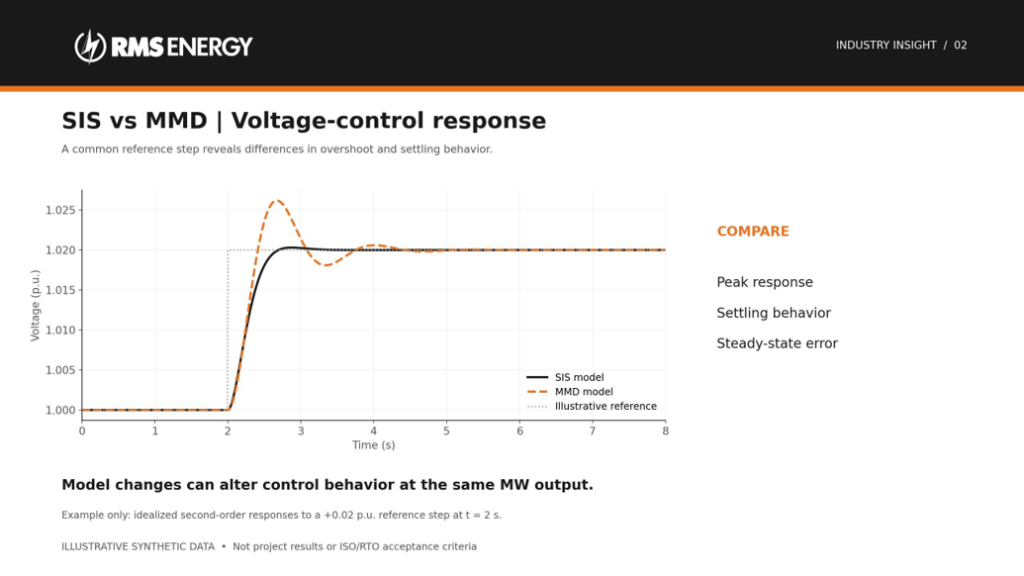
Figure 2. Synthetic voltage-control responses to an illustrative reference step. The example is not a prescribed ISO/RTO test or tolerance.
The comparison should also examine oscillation decay. In the illustrative traces below, both signals approach the same final active-power value, but their damping differs. Actual findings depend on the validated models, network conditions, and applicable study criteria.
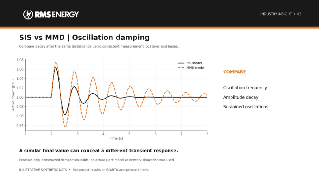
Figure 3. Constructed damped sinusoids illustrate different transient responses. These traces were not produced by a plant or network simulation.
That observation does not establish a violation or a Material Modification. It identifies the questions the study team must resolve: whether the new response meets applicable requirements, whether previous conclusions remain valid, and whether other projects or required upgrades are affected. The formal outcome belongs to the applicable regional review process.
The evidence developers should prepare
RMS Energy recommends maintaining a single change package that connects the commercial decision, electrical design, and submitted models:
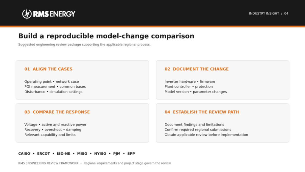
Figure 4. RMS Energy framework for preparing a reproducible comparison and establishing the applicable review path. The regional requirements discussed above govern each project.
- Document the change precisely. Identify the original and proposed equipment, firmware, controller versions, settings, unit count, ratings, and implementation date. Obtain the OEM’s explanation of any effect on electrical behavior.
- Reconcile the models. Update power-flow, short-circuit, positive-sequence dynamic, and EMT representations as applicable. Check that plant and inverter controllers, protection, operating modes, and network impedances represent the same configuration.
- Provide reproducible evidence. Compare the original and proposed configurations using consistent operating points and disturbances. Include relevant reactive-capability, ride-through, recovery, and stability results. Apply the regional test scope and acceptance criteria.
- Resolve the approval path and schedule. Confirm the required request, submission window, deposit, study scope, and agreement amendments with the operator and transmission owner. Build that work into procurement and commissioning milestones.
- Close out the field implementation. Record the accepted configuration, reconcile commissioning settings with the models, and submit required as-built or as-left evidence. A model submitted after installation does not substitute for required prior review.
Where control tuning is necessary, involve the OEM. NERC’s EMT guidance recommends OEM participation or direct authorization because a parameter adjustment can have consequences beyond the issue being investigated. [1]
Make the interconnection review part of the equipment decision
Inverter and controller changes can improve performance, solve supply constraints, or support reliable operation. Their value is strongest when the project also understands the associated study and approval obligations.
Before approving the substitution, the project team should be able to identify the changed electrical behavior, the applicable regional review path, and the evidence supporting implementation. That discipline gives developers a more credible schedule and keeps the plant, its models, and its interconnection commitments aligned.
Learn how RMS Energy supports complex transmission projects here: T&D engineering and consulting services
#GeneratorInterconnection #MaterialModification #InverterBasedResources #EnergyStorage #PowerSystems #RMSEnergy
Official sources
1. NERC Recommended Practices for Performing EMT System Studies for IBRs. December 2024; control interactions and OEM involvement in tuning.
2. CAISO Generator Management BPM. Version 40; Sections 6.1, 6.2, 6.4, 6.6 and post-COD provisions. Current manual available from this page.
3. CAISO Appendix DD and Appendix KK. August 5, 2026 versions; applicable modification provisions in Section 6.7.2.
4. ERCOT Planning Guide Section 5. August 1, 2026; Sections 5.2.1, 5.3.2.5(9), and 5.5(6).
5. ISO New England PP5-6 Appendix E — Procedures for Material Modification Determinations, pages 57–60. Official ISO-NE PDF, effective October 11, 2025. Project-stage thresholds, data milestones, and technical screening criteria.
6. MISO Attachment X Generator Interconnection Procedures. Section 4.4 and Permissible Technological Advancement definition.
7. MISO Facility Modification Requirements. Sections 1–3 and FAQs, referencing BPM-015 Sections 6.7.1 and 6.7.4. Used for the report package, phase-specific studies, submission timing, and assessment criteria.
8. NYISO Attachment HH Section 40.6. Sections 40.6.3 and 40.6.3.7, including the technological-change submission deadline.
9. PJM Manual 14H. Revision 07, August 19, 2026; Sections 9.7.3 and 9.8.5.
10. SPP Attachment V Section 4. Current posted tariff, effective July 20, 2026; Sections 4.4.3, 4.4.4, and 4.4.6.
11. SPP Generator Interconnection Manual BP 7250. September 25, 2025 version; Section 7.7 and replacement-process distinctions. Apply the governing tariff if provisions differ.