
EMT Model Quality Testing Across ISO and RTO Markets
RMS Energy Industry Insight | Part 3 | September 2026
Submitting a PSCAD model is only part of the job. The next question is whether that model can support credible interconnection studies: does it initialize correctly, respond to disturbances as intended, and represent the equipment that will actually be installed?
For project developers, model quality testing belongs in the interconnection schedule and the OEM scope of supply. A missing test report, inconsistent controller setting or unexplained mismatch between simulation platforms can require another round of model development before the study can proceed.
This third article in our Beyond Positive-Sequence Analysis series examines model quality testing across PJM, MISO, ISO New England, NYISO, ERCOT, SPP and CAISO. The evidence requirements differ by region, facility and project stage. There is no single national MQT checklist.
What model quality testing needs to establish
A model that runs without a software error can still be unsuitable for a system study. It may settle to the wrong operating point, omit protection, use default plant-controller settings, or behave differently from the model submitted in another platform. Model quality testing makes those weaknesses visible before they become study assumptions.
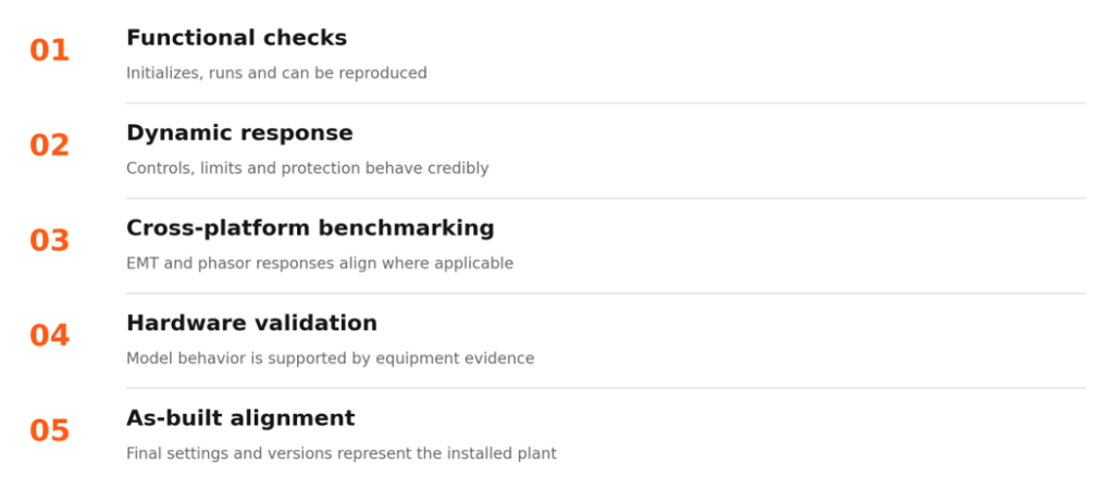
Figure 1. Five complementary types of evidence. This is an engineering framework, not a universal ISO/RTO test sequence.
Functional checks establish that reviewers can execute and reproduce the model. Dynamic tests examine its response to changes in voltage, frequency, dispatch, faults and grid strength. Cross-platform benchmarking checks consistency between EMT and positive-sequence representations for comparable conditions.
Hardware validation answers a different question: does the model represent the actual controller or device? As-built verification then connects the submitted parameters and versions to the installed plant. Agreement between two software models alone does not establish either of those facts.
A test can also reveal a genuine equipment or control limitation. The appropriate response is to understand and resolve the behavior, not to tune the model simply to make the plots look acceptable.
The Requirements Are Converging—But They Are Not Identical
Across the regional documents reviewed here, a common engineering direction is evident: an EMT submission needs evidence that the model is usable, responds credibly and represents the intended equipment. This is convergence in the questions being asked, not a single harmonized acceptance standard. [1–6, 8]
Common expectations across regional test programs
- Clean initialization and a stable starting operating point, without unexplained drift or numerical artifacts.
- Credible responses to voltage and frequency changes, faults and control-reference changes, with the relevant controls, limits and protection represented.
- Evaluation of the operating modes and grid conditions specified for the resource, including charging and discharging for storage where required.
- Reproducible cases, documented parameters and plots that allow the reviewer to understand what was tested and why the result is acceptable.
- Consistency between EMT and phasor-domain models for designated tests, and hardware or field evidence where the applicable procedure requires it.
These are recurring themes, not a claim that every ISO/RTO requires every item for every project. Grid-strength tests, phase-angle tests, hardware validation and cross-platform overlays have different applicability and acceptance rules. [1–6, 8]
Regional differences still determine acceptance
The required platforms and model types differ. A PSCAD-to-PSS/E comparison does not automatically satisfy a scope that also requires TSAT, and a library model may not substitute for a user-defined model. Regions also differ in which disturbances must be benchmarked, the prescribed network equivalent, operating points, fault profiles, measurement locations and required simulation duration. [1–5]
The meaning of a passing result also differs. ISO New England separates model performance from benchmarking criteria. NYISO uses qualitative comparison rather than one universal numerical error envelope. ERCOT distinguishes MQT from unit hardware validation. A passing software-to-software comparison therefore cannot be assumed to satisfy every validation obligation. [3–5]
Timing matters as well. Initial study models, revised design models and as-built packages may require different evidence. Adopted requirements must remain separate from proposed changes, including the expanded framework in SPP’s September 2026 stakeholder materials. [1, 2, 7]
For developers, the practical approach is to build a reusable core test library and maintain a regional compliance matrix alongside it. Map each required test to the applicable procedure, model version, operating mode, acceptance criterion and submission milestone. That supports reuse without assuming that acceptance in one market transfers to another.
How the seven markets compare
The table summarizes the testing approach, not universal applicability to every facility. Consult the cited documents and project-specific instructions for the governing scope, deadline and acceptance criteria.
| Market | Testing approach | Important distinction |
| PJM | Defined PSCAD MQT and designated PSS/E benchmarks | As-designed and as-built evidence differ; some implementation dates remain pending in the cited guideline. [1] |
| MISO | Structured tests and overlays across required platforms | Appendix I applies to DPP 2025 and later; model packages mature through development and commissioning. [2] |
| ISO New England | Detailed IBR model acceptance tests | Separate performance and benchmarking criteria; not every test requires an overlay. [3] |
| NYISO | Defined EMT test suite with applicable phasor comparisons | Qualitative consistency and explanations matter; applicability differs for non-IBR facilities. [4] |
| ERCOT | Model quality tests plus separate unit validation | Technology-specific requirements and PSS/E, PSCAD and TSAT comparisons, with stated exceptions. [5] |
| SPP | Current EMT requirements and test checklist | Broader multi-platform requirements in September 2026 materials are proposals, not current mandates. [6, 7] |
| CAISO | EMT model documentation and response testing | Requirements already exist; the cited guideline is not a universal PSS/E overlay matrix. [8] |
Requirements and source versions reviewed for September 2026. Proposed requirements are identified explicitly.
The practical lesson is to scope testing region by region. Reusing the same OEM model may be appropriate; reusing the same test report without checking the regional requirements is not.
PJM and MISO
PJM distinguishes model development stages
PJM’s March 5, 2026 EMT Model Development Guidelines define functional and ride-through tests covering initialization, setpoint and frequency changes, faults, voltage excursions, grid strength and phase-angle changes. Battery and hybrid configurations require attention to the specified operating modes rather than a single generation case. [1]
The benchmarking requirements are stage-specific. As-designed comparisons use designated tests against an applicable PSS/E representation. The as-built section calls for PSCAD comparisons with both the latest PSS/E user-defined and library models, together with parameter verification. Not every EMT test is a cross-platform benchmark. [1]
Applicability and implementation timing require care. The guideline identifies Decision Point II submissions for applicable Cycle 1 and later inverter-based resource projects connected to the bulk power system, with screening provisions for Transition Cycle 2. It also states that implementation dates for specified non-cycle and as-built submission requests will be communicated in a later revision. Those provisions should not be presented as universally effective deadlines. [1]
For developers, the immediate action is to confirm the project’s submission category and require the OEM to supply the models, cases and settings needed for that stage.
MISO connects model quality to the project lifecycle
MISO’s BPM-015, Revision 33, effective July 1, 2026, incorporates a structured IBR modeling framework in Appendix I for DPP 2025 and later projects. DPP 2025 has transition provisions; later cycles bring the initial modeling package into the application process. [2]
The framework includes initialization, balanced faults, small voltage and frequency changes, voltage and frequency ride-through, protection and short-circuit-ratio tests, with a separate PSCAD phase-angle test. Required comparisons use aligned voltage, frequency, active-power and reactive-power plots at the measurement point. Significant discrepancies need a technical explanation and may lead to rejection if they are not justified. [2]
Model delivery continues after the initial study submission. Applicable updates are tied to project changes and decision points, with as-built models due before commercial operation and as-left updates following changes. Developers should budget for repeated testing as the design becomes final, rather than treating MQT as a one-time OEM deliverable. [2]
ISO New England and NYISO
ISO New England separates performance from benchmarking
ISO New England’s Planning Procedure 5-6 and Appendix C2 establish detailed IBR model acceptance tests. These address the model’s own performance as well as agreement between PSS/E and PSCAD for designated scenarios. The two forms of acceptance should not be conflated. [3]
A model can show an acceptable individual response while still disagreeing with its counterpart because of different control modes, current limits, protection settings or plant aggregation. Conversely, the absence of identical fast transients does not automatically mean the models are inconsistent; their mathematical representations are different.
Appendix C2 specifies which tests require benchmarking. Phase-angle and certain grid-strength evaluations are not a reason to impose an identical overlay rule on every test. Storage also requires attention to charging and discharging conditions. [3]
Developers should request a test-by-test compliance matrix with results, assumptions and exceptions. Acceptance in a simplified test system does not establish acceptable interactions with the actual surrounding network; that remains a system-study question.
NYISO requires interpretable evidence
NYISO’s EMT Modeling Guideline, Version 2.0, issued in June 2025, defines a test suite that includes initialization, balanced and unbalanced faults, overvoltage, control-reference changes, frequency response and ride-through, phase-angle changes, grid strength and voltage protection. Applicability varies for conventional and non-generation facilities. [4]
For applicable tests, EMT responses are compared with the latest phasor-domain model. The guideline uses qualitative comparison rather than a single numerical error envelope for all cases. The report must make differences understandable, including distinctions associated with the higher bandwidth of EMT simulation. [4]
That does not make every discrepancy acceptable. A different steady-state operating point, inconsistent slower response or unexplained recovery trend can indicate a modeling or settings problem. A credible submission explains the cause and demonstrates that both models represent the intended plant behavior.
The useful deliverable is a reproducible engineering report: the operating point, network equivalent, controller mode, disturbance, plotted channels and conclusion for each test. A folder of unlabeled plots does not provide the same evidence.
ERCOT and SPP
ERCOT distinguishes quality tests from unit validation
ERCOT’s Dynamics Working Group Procedure Manual, Revision 24, distinguishes model quality tests, unit model validation and model maintenance. The MQT framework includes comparisons among PSS/E, PSCAD and TSAT user-defined models where required, with technology-specific tests and stated exceptions. Phase-angle testing is PSCAD-specific. [5]
Unit model validation is a separate task. For applicable inverter models, it compares the model with actual inverter hardware behavior. This device-level evidence is not replaced by matching two simulation platforms, and it is not identical to site-specific plant verification. The manual also addresses maintaining models and documenting as-built settings. [5]
A developer therefore needs separate deliverables for model execution, cross-platform consistency, device validation and final plant configuration. The responsibilities may involve the inverter supplier, plant-controller supplier, consultant and commissioning team. Their scopes should identify who supplies each piece of evidence.
SPP has current requirements and a broader proposal
SPP’s EMT Model Requirements, Revision 1, dated March 10, 2023, already address practical model usability and testing. The document covers matters such as initialization, simulation behavior, multiple model instances and representative disturbance tests. It also explains that the basic test checklist does not by itself establish compliance with all performance requirements. [6]
For models that do not use the actual controller code, the current requirements call for hardware validation; comparison against another software model alone is insufficient. This is an important distinction for developers purchasing an EMT model as a standalone file. [6]
Separately, September 16, 2026 Generator Interconnection Advisory Group materials include proposed expanded modeling requirements. These describe a broader multi-platform framework and more explicit lifecycle expectations. The draft includes unresolved effective-date and revision placeholders. It should be discussed as a proposal, not as an adopted obligation. [7]
Developers can use that proposal to assess contract flexibility and future model availability, while continuing to base current compliance decisions on adopted requirements and project-specific instructions.
CAISO and the limits of benchmarking
CAISO already requires EMT model testing evidence
CAISO should not be described as having no EMT model quality requirements. Its April 14, 2021 EMT Modeling Requirements include model documentation and response testing, including balanced and unbalanced faults and relevant voltage, reactive-power, frequency and active-power changes. The guideline also addresses validation evidence for models that do not use actual controller code. [8]
The distinction is one of structure. This document is not the same as a universal PSS/E-to-PSCAD overlay matrix covering every project and every test. CAISO and the applicable transmission owner may impose additional study-specific requirements. The absence of a document titled “MQT” does not mean the absence of a model-testing obligation. [8]
Developers should confirm both the required delivery milestone and the evidence accompanying the final model. An as-built submission is useful only when its settings and software versions can be traced to the equipment in service.
Matching waveforms requires engineering judgment
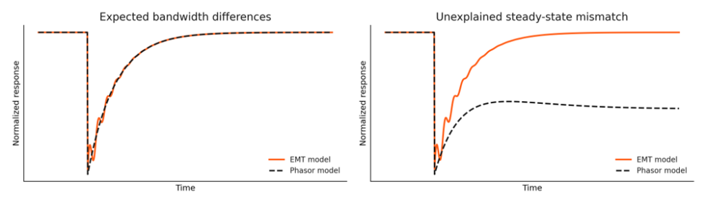
Figure 2. Conceptual traces only; not measured or simulated project results. No ISO/RTO acceptance tolerance is implied.
Positive-sequence models and EMT models do not represent the same frequency range or every physical phenomenon. Fast detail visible in EMT may be absent from the phasor response. The objective is appropriate consistency under the prescribed test, not artificial point-by-point agreement at all times.
Start with identical operating points, disturbance definitions, control modes, measurement locations and relevant parameters. Then investigate discrepancies. Differences in steady-state values or slower control response often warrant a different explanation from high-frequency EMT detail.
Acceptance criteria must come from the applicable regional procedure and study scope. Neither a generic percentage-error threshold nor visual similarity should replace those criteria.
What developers should require from model suppliers
Model quality is easiest to manage when it is addressed before equipment procurement is complete. The contract should identify the regional requirements, delivery stages, required platforms and responsibility for correcting rejected submissions. Our recommendation is to make the test evidence an explicit deliverable alongside the model files.
- Executable model packages, required software versions, libraries, dependencies and clear installation instructions.
- A plant-specific parameter record covering the inverter, plant controller, protection, aggregation and network representation.
- A regional test matrix with operating modes, disturbances, acceptance criteria, results and any justified exceptions.
- Reproducible test cases and scripts, labeled output channels, and the underlying data used in the report.
- Cross-platform overlay plots for the required tests, with an explanation of material discrepancies.
- Hardware-validation evidence where required, clearly distinguished from software-to-software benchmarking.
- A change log and defined retesting process for firmware, controller settings, protection or equipment changes.
- An as-built handover that reconciles submitted parameters with commissioning records and final field settings.
For battery and hybrid projects, agree on the necessary operating modes early. Charging, discharging, simultaneous resource operation and plant-controller interactions may require different cases. A passing result in one configuration should not be assumed to cover all configurations.
Assign one party to reconcile the entire package. The inverter vendor may supply a valid device model while the combined plant model still contains inconsistent controller settings or aggregation assumptions. The project needs both pieces to work together.
The next question for every EMT submission
The first two articles in this series asked why EMT matters and when it is required. The next question is whether the submitted model comes with enough evidence to support the study decision.
For developers, the priority is practical: confirm the regional test scope, obtain reproducible evidence, resolve material discrepancies, and keep the model aligned with the plant as it moves through design and commissioning. That work makes model acceptance more predictable and gives engineers a stronger basis for evaluating real system behavior.
When your next EMT package arrives, ask for more than the PSCAD file. Ask what was tested, what the results establish, and how the model will be kept current.
Learn how RMS Energy supports complex transmission projects through our T&D engineering and consulting services
Official sources
Primary-source references for the article. Requirements vary by facility, queue cycle and project-specific direction. Publication dates and document revisions below identify the cited basis; proposals are explicitly labeled.
1 PJM EMT Model Development Guidelines
March 5, 2026. See applicability, MQT and as-designed/as-built benchmarking sections.
2 MISO BPM 015 Generator Interconnection
Revision 33, effective July 1, 2026. Appendix I addresses IBR modeling requirements; ZIP contains the manual.
3 ISO New England Planning Procedure 5 6 Appendix C2
IBR Model Acceptance Tests, Revision 1.0. Read with PP5-6 and Appendix C1 EMT requirements.
4 NYISO EMT Modeling Guideline
Version 2.0, June 2025. Testing requirements and applicable EMT/phasor comparisons.
5 ERCOT Dynamics Working Group Procedure Manual
Revision 24, June 2025. Sections 3.1.5 through 3.1.7 distinguish MQT, unit validation and maintenance.
6 SPP EMT Model Requirements
Revision 1, March 10, 2023. Current model requirements and test checklist cited in the article.
7 SPP Generator Interconnection Advisory Group materials
September 16, 2026. Proposed expanded modeling framework; not an adopted requirement. ZIP meeting package.
8 CAISO Electromagnetic Transient Modeling Requirements
April 14, 2021. Model documentation, response testing and validation expectations.